
Modern ESCs usually have a Low Voltage Cutoff (LVC) circuit to prevent over-discharge of the flight battery. However, it may be useful to have a warning that voltage is getting low before the motor cuts out. Also, the LVC may cut in at a lower voltage than the cells are designed for (eg. a 3 cell Li-ion pack should not be discharged below 9V, but the ESCs LVC may cut in at about 5.4V).
This circuit is very simple to make, having only six components which can be wired up 'dead bug' style (no circuit board required!). The heart of this design is the TL431 active Zener. When the voltage between terminals 1 and 2 exceeds 2.5V, it draws current through terminal 3, shorting out the LEDs. Two LEDs are required because the TL431 has a minimum 'on' voltage of 2V, which is not low enough to extinguish a single LED (having two LEDs is also useful for increasing visibility). The cutoff point is set by the ratio of R2 and R3. 6V is appropriate for a 7 cell Nicad or 2 cell Li-ion pack, 7.2V for an 8 cell Nicad, and 9V for a 3 cell Li-ion battery.
Resistors R2 and R3 should be 1% tolerence for accuracy. Alternatively, a variable resistor could be used to adjust the cutoff voltage. Point the LEDs in opposite directions so they can be seen from both sides of the model. The LEDs should be 'Super-bright' types for best visibility. Even so, they may be hard to see outside on a bright day.
The next circuit increases visibility by flashing the LEDs, and also includes an audible warning. Once again a TL431 is used, but this time it acts only as a 2.5V reference. Voltage sensing and other functions are achieved using an LM339 quad comparator IC. When battery voltage drops below the preset alarm value, IC2/1 switches its output off, allowing the 2Hz oscillator (IC2/2) to flash the LEDs. This signal is then inverted by IC2/3, which pulses a 5kHz oscillator (IC2/4) in step with the LEDs. The 5kHz output is fed into a small peizo-electric speaker to produce a piercing, high-pitched beeping sound.

The flashing rate can be altered by changing C2 or R7 (higher values lower the rate). You might also wish to tune the audio frequency by adjusting C3 or R13, to optimize output from the peizo speaker. Due to the larger number of components, this design should be built on a circuit board. Using conventional components it weighs about 30 grams (1oz) which is a bit heavy for most indoor models. However, a version using smd components could be made much lighter.
A flexible and sophisticated alarm could be made using a microcontroller with A/D or comparator inputs. Cutoff voltage could be calculated from the initial voltage at switch-on. Multiple LEDs could be turned on or flashed at different rates to indicate the battery's state of charge. It could even play a unique tune so you know it's your model that needs to land!
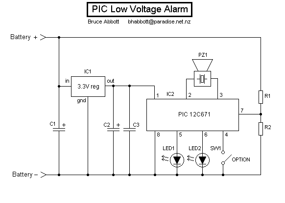
In my proposed circuit, a Microchip PIC12C671 would be powered by a 3.3V regulator, which also acts as a voltage reference. The PIC is set to use its internal RC oscillator, making 6 pins available for I/O. The raw battery voltage is proportionally reduced to a level that the PIC can handle, and input through pin 7 (AN0). Four general purpose outputs on pins 2,3,5 and 6 can drive LEDs or a speaker (push-pull speaker output for greater volume). Pin 4 (MCLR) can only be used as an input, so it is wired to a switch which can be interrogated to select one of two options (eg. cutoff voltage, tune). The physical circuit is quite simple and should be easy to make. As for the software, it's 'just' a matter of developing a program and burning it into the PIC . . . ahem!
