Lithium-Ion cells require a constant voltage, current limited charge. The voltage must be accurately limited to 4.2V, as higher voltage reduces cell life. This circuit is designed to meet these requirements using standard components.
Q3 and Q4 form a quasi-PNP transistor which has very high current gain. This is turned on by resistor R7, and feeds charging current to the Li-ion cell through R9. Q2 turns on when voltage across R9 reaches about 0.6V, and robs Q3 of bias, therefore stabilising output current to approximately 0.6V/R9.
As the cell charges its voltage rises. Active Zener IC1 senses the cell's voltage through the voltage divider R6-R5-VR1. The Zener turns on when its input voltage reaches 2.5V, increasing voltage drop across R3. This causes Q2 to be turned on harder through R4 and D1, reducing output current just enough to hold the output voltage at 4.2V (D1 prevents output current being affected by the Zener when it is turned off). C1, C2 and C3 are included to ensure stability at high frequencies.
LED1 provides an indication of charge status. Q1 needs 0.6V between its base and emitter to turn on, as does Q3. Therefore the voltage across R1 tracks that across R9, causing LED current to be proportional to charging current (R1 sets maximum LED current to about 6mA). As cell voltage approaches 4.2V and output current drops, so LED brightness reduces until it is almost extinguished. If the cell is disconnected there is no current through the LED and it remains dark.
The parts can be wired onto tag-strip or matrix board. Q4 should be mounted on a heatsink, or you could bolt it onto a metal case (use an insulator to avoid shorting the collector to ground!). Substitute transistors can be used. Just about any small signal PNP type can be used for Q1-Q3, and a medium power NPN type for Q4.
I designed this PCB with Eagle Layout Editor from CadSoft. Note that I have not yet made one of these boards, hopefully there are no errors in it! The bottom layer is ready to print actual size at 600dpi. If you can't get the GIF image to print properly, download this zip archive containing the Eagle board file and BMP image (BMP images do print full size with Kodak/Wang Imaging in Windows98, but not with Windows Paint!).
 |
 |
Choose an appropriate value for R9 (a switch could be wired in to select different currents). Current should be set for a charge rate of 1C or less ie. equal to the cell's capacity in Ampere-hours. Adjust VR1 for an output voltage of exactly 4.20V with nothing connected. Now connect the cell and wait for the LED to dim (a full charge should take 1.5 to 2 hours). Verify that cell voltage never exceeds 4.2V, as too much voltage could damage the cell. To power the circuit you need a DC power supply of at least 6V, with enough current capacity for the charge current you are using. Higher input voltage is OK so long as the heatsink is large enough to cool Q4 properly.
Do not leave a cell connected without input power on, as this will cause the cell to gradually discharge. A cell whose voltage has dropped below 2.5V must not be charged at full current. You could try reviving it by trickling in a few milliamps until voltage reaches 3V, but it will probably be irreversably damaged.
Due to strict voltage requirements, charging Li-ion cells in series is not recommend. If you are sure that all the cells in your pack have exactly the same voltage, you can modify the charger for higher voltage (simply increase R6 to get the required voltage eg. 7k6 for 8.4V = 2 cells). However, you should regularly check the cells for voltage missmatch, and charge them individually if there is more than 0.05V of imbalance.
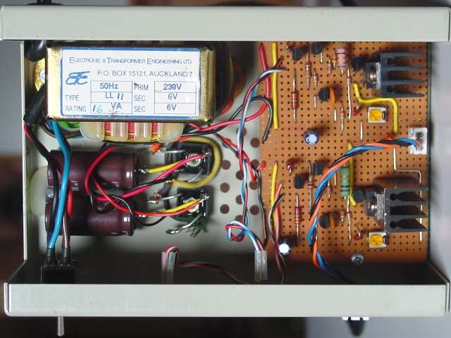
My solution to the imbalance problem is to put a third wire in the battery pack, connected to the center of the two cells. I made up two chargers which are independantly connected to each cell. Two power supplies are also required, with floating outputs. This was achieved using a transformer with dual 6V windings, feeding two bridge rectifiers and filter capacitors.
Another way to ensure charge balance would be to have each cell wired separately, so that they can be connected in parallel for charging, and in series for flight. This requires a 4 pin battery connector for 2 cells, and 9 pins for 3 cells.
 |
 |
Lithium is a dangerous metal. It ignites spontaneously in water and burns hot enough to melt steel! In ionic form it is safe, but an overheated battery could burst into flames and be very hard to put out. This can happen if the cell gets too much voltage across it. Do not try to charge a cell which is bulging or leaking. Avoid shorting out cells. Until you have verified that your charger works reliably, do not leave it unattended while charging. Use an accurate digital voltmeter to check the voltage calibration occassionally. When charging, place the cell on a fire-retardent surface, in good ventilation away from combustable materials, and have a smoke alarm installed nearby.