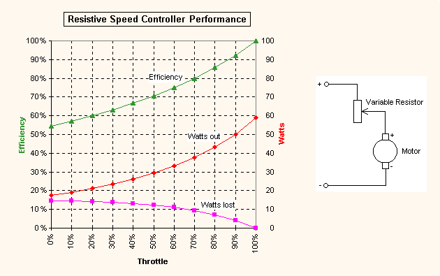
The purpose of an Electronic Speed Controller (ESC) is to convert fixed battery voltage into a variable voltage for controlling the speed of a motor. The obvious way to do this is simply add a variable resistor in series with the motor, mechanically operated by a servo. R/C cars often use this technique. However, this is inefficient at low throttle settings, resulting in a lot of power wasted in the controller. A large wirewound resistor is required to dissipate the heat generated. Throttle response is non-linear, becoming markedly less effective towards minimum throttle. To provide a complete cutoff the wiper must be moved beyond the end of the resistance track.
Mechanical speed controllers are not very suitable for electric flight, due to their size, weight, poor efficiency and unreliability. The graph below shows the calculated results for a Speed-400 class motor powered from an 8.4V (7 cell) battery. In this example I have assumed a load of 1.2 Ohms, giving maximum power output of 59 Watts. The speed controller's resistor is variable from 0 to 1 Ohm. At full power efficiency is excellent, but it gets progressively worse as the throttle is reduced. At half power (level flight for a typical model) 30% of the the battery's energy is wasted. Up to 14 Watts of power must be dissipated by the resistor.

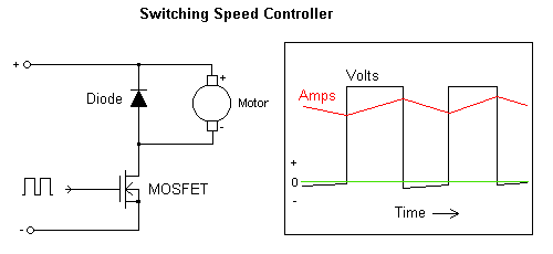
How can we improve on this design? We can improve reliability by replacing the variable resistor with a power transistor, and save weight by swapping the servo for a solid state driver. However, the power transistor still needs to get rid of 14 Watts of heat, so it must be bolted to a large heatsink. To improve efficiency and reduce controller heating, we need to use a switching controller. Instead of simply limiting current continuously, the switching controller sends short pulses of full power to the motor. If the pulse rate is high enough, the motor's inertia will cause it to respond to the average current. To vary average current we can adjust the duty cycle (ratio of ON to OFF). At any instant the switching transistor is either fully ON (0 Ohms) or fully OFF (infinite Ohms), so it theoretically dissipates no power! In practice power dissipation is determined by the transistor's on-resistance, and the time it takes to switch on and off (which should be as small as possible). There is some extra power loss in the motor at low throttle, due to peak current being higher than the average. This can be minimized by increasing the switching frequency until inductance in the motor windings causes the current pulses to be smoothed out. However, it does not pay to increase the frequency too far, or switching losses in the transistor will become significant.
Modern designs use a MOSFET (Metal Oxide Semiconductor Field Effect Transistor), which is turned on by applying a voltage to its gate. MOSFETs are available with very low on-resistances (as low as 0.002 Ohms!), and gate threshhold voltages of less than 2V. A bipolar transistor could be used, but it would require a wasteful current drive of up to 20% of its output current, and on-resistance would be worse than a good MOSFET.

When the MOSFET is turned on, current ramps up as the magnetic field in the motor windings increases. When the MOSFET is turned off, magnetic energy stored in the windings has to be absorbed by the ESC. By wiring a diode across the motor, we return the energy back into the motor as current, which ramps down as the magnetic field collapses (without a diode the current would drop rapidly, but a large voltage spike would occur which could damage the MOSFET). For best efficiency the diode should drop as little voltage as possible. Therefore a high-current Schottky diode is usually specified. If the switching frequency is high enough then current flow will be mostly DC (Direct Current), with just a small triangular ripple. Thus the motor acts like it was fed a constant voltage, rather than the actual rectangular on/off voltage waveform.
Many ESC's now use Synchronous Rectification, a technique that replaces the Schottky diode with another MOSFET. It is switched on when the main MOSFET is off. This has lower loss than a diode, and can cost very little as the same circuit can be used to provide a brake function.
"High Rate" controllers operate at frequencies of 500Hz to 3KHz, which is satisfactory for most conventional cored motors. Coreless motors have very little winding inductance, and will not smooth out the current enough. For these motors a much higher frequency should be used (up to 60KHz), possibly combined with an external LC filter. Older ESC designs commonly used "Frame Rate" frequency (50Hz), simply because it was easier to make a circuit that was syncronized to the incoming radio control pulses. This is not optimal even for conventional cored motors, and can result in excessive motor heating at low throttle settings.
Throttle Control Response
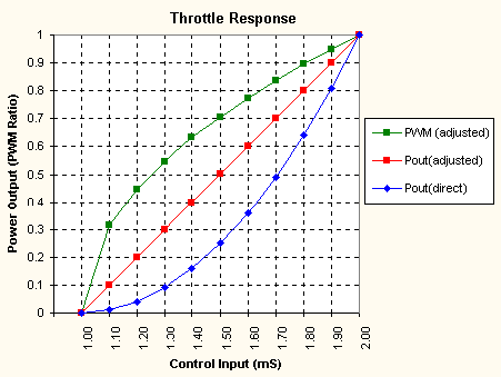
If throttle stick movement is linked directly to pulse ratio output, the stick will have most effect at the top end, with little response below half way. The reason for this is that although pulse ratio is proportional to the stick movement, this affects both voltage and current in the motor. Since power is equal to voltage multiplied by current, we should compensate by applying a reverse exponential function. This can be done by programming a small microprocessor with the required response.
The graph below shows how direct translation of input pulse width to PWM ratio yields a non-linear power output curve (blue). By applying a compensating reverse exponential PWM function (green), we achieve a linear power output curve (red).

Battery Eliminator Circuit (BEC)
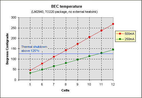
As its name suggests, a BEC is designed to eliminate the need for a separate receiver battery. A low-dropout 5V linear regulator IC is often used for this purpose, typically supplying up to 1 Amp of current to run the receiver and servos. The regulator absorbs the difference in voltage between the motor battery and the receiver's nominal 4.8V requirement. As current is drawn so the regulator converts excess power to heat. The graph below shows how hot it will get for various currents and cell counts.

If the regulator gets too hot it will shut down, causing loss of control (which would be very bad for your plane's health!). For an LM2940 with no heatsink, I suggest a limit of 10 cells when driving 2 servos, and 7 cells for 4 servos. This is not exact because average servo current depends on flying style and mechanical loading. However, the cooler you keep the regulator, the more reliable it will be. Adding a heatsink and/or putting the regulator into the airflow will make a big improvement.
BEC overheating is a problem with high cell counts. Methods of dealing with this include:-
Low Voltage Cutoff (LVC)
The function of an LVC is to prevent the motor battery from being completely discharged. There are two main reasons for this, to avoid damaging the cells, and to make sure enough voltage remains to operate the ESC (this is especially important if a BEC is used, as power to the receiver and servos is supplied from the motor battery). The LVC may also help to minimise damage caused by overcurrent, caused by events such as the propellor striking the ground, gearbox seizure or motor failure.
When an under-voltage condition is detected, the LVC circuit stops the motor. This allows the battery to recover, ensuring that there is enough capacity to maintain BEC operation. The pilot should be aware that the motor can stop without warning. The LVC can be designed to reset by throttling back to zero, allowing another short burst of 'emergency' power (preferably at a lower throttle setting).
Instead of stopping the motor completely, the LVC could reduce power to maintain the battery voltage. This alerts the pilot that the battery is low while still having something left for landing. Power reduction can be achieved by proportionally reducing the throttle setting, or simply stopping the motor and then restarting it when voltage rises again ('Fuzzy Logic' algorythm). One possible disadvantage of these techniques is that the battery could run almost completely flat if the pilot doesn't notice the drop in power (dangerous in a glider where motor run to high altitude is followed by thermalling for a long time).
Unfortunately, many commercial ESCs have no way to program the low voltage cutoff point, but simply assume a fixed value of about 6V. Whilst this does ensure enough voltage to operate the BEC, it allows over-discharge of batteries that have more than 7 cells. Ideally, the LVC should operate when voltage falls below 0.9V per cell. Setting the cutoff voltage can be achieved by hard-wiring the ESC for the voltage required, or with a switch or movable link, or by measuring the battery voltage at startup to determine the number of cells being used. MPUs are now available with built-in A/D convertors, which makes automatic cell count determination quite easy.