The Problem
Certain miniature receivers, such as the Hitec Feather and GWS R4P, are particularly sensitive to noise and interference. This may be tolerable in a slow-flyer, but a fast aerobatic model requires a reliable signal at all times.
Traditional PPM (Pulse Position Modulation) decoders use a shift register or counter to separate out the channels. Short noise spikes can cause the decoder to 'jump' to the next channel, shifting all subsequent channels across (thus aileron becomes elevator becomes throttle etc). More severe noise bursts cause random output on all channels.
The Solution
I simply replaced the existing decoder with a PIC microcontroller, programmed to duplicate the original decoding function but reject any pulses that don't 'look right'. The circuitry is very basic, just the 8 pin microcontroller and an optional status LED. All the tricky stuff is done in software. For the prototype I used a PIC12F675 mounted in an IC socket, so that I could remove it for re-programming. When the software has been proved, this will be replaced with a much smaller surface-mount chip.

How it Works
On startup, all outputs are set Low, and the status LED flashed to indicate power on. Then the PPM signal is monitored on pin 4. Firstly, wait for a sync gap of at least 2.5mS, then wait for the signal to go high (this should be the start of the first channel). Now measure the time until the signal goes low. The pulse width should be between 0.18mS and 0.7mS. Too short or too long indicates a glitch. If the pulse is OK, continue timimg until the next pulse starts, which should be between 0.75mS and 2.3mS. Once again, anything outside this range is considered to be invalid. Store the measured time as Channel 1, and process the next 3 channels similarly.
After receiving 4 channels, light the status LED to indicate a good signal, and generate servo outputs. By this time the incoming PPM frame should be almost complete, so loop back to wait for the next sync gap. To reduce the effect of noise, each channel's time is averaged with that of the previous good frame. This reduces the amount of servo jitter on a weak signal. When several consecutive good frames have been detected, the signal is assumed to be stable, and the current frame is stored for failsafe.
In the event of a glitch being detected, the entire frame is skipped. If a previous good frame is available, that is output instead. The servos will hold their last positions until the noise burst is over. If there are too many consecutive bad frames, the decoder goes into failsafe mode. This returns the servos to their neutral positions.
The Software
Version 1.3 is available for download. Source Code, HEX files.
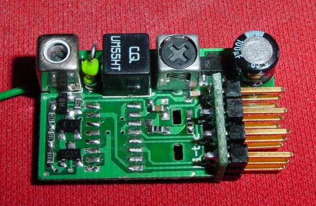
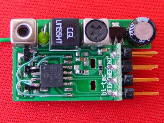
Installing the Decoder into a GWS R4P/H Receiver
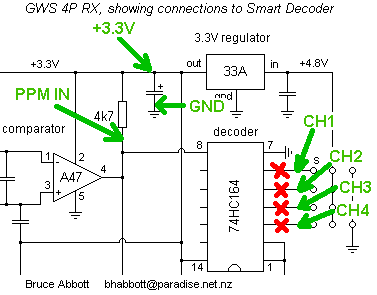
Cut off each servo signal pin between the board and the connector, isolating it from the onboard decoder chip. Identify the +3.3V, Ground, and PPM signal lines on the circuit board (refer to the circuit above and picture below). Carefully solder thin wires to these points, then route the wires to the correct pins on the PIC chip. If desired, wire the status LED and resistor to pins 1 and 2. Finally, wire pins 3,5,6, and 7 to the servo signal pins.
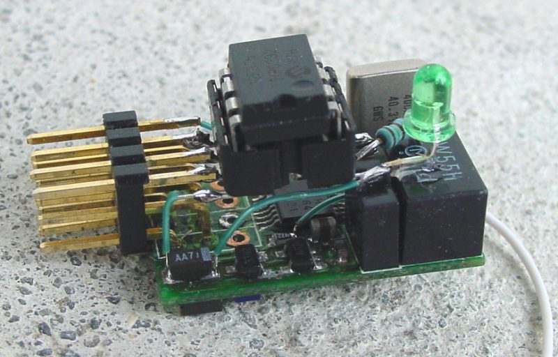
Installing the Decoder into a Hitec Feather Receiver
To maintain the Feather's compact size you need a surface-mount PIC chip. This can be inserted into a conventional PIC programmer with a suitable adapter. The PIC replaces the Feather's existing decoder, a CD4015 shift register IC.
Unsolder and remove the crystal daughter-board. The CD4015 can be removed by cutting through its pins with a sharp knife, and unsoldering the remains from the PCB. Now carefully bend pins 1~4 of the PIC12C509 so they are horizontal. Solder pins 5~8 to pads 14~17. Using thin insulated wire, Connect pin 1 to pad 16, pin 3 to pad 9, and pin 4 to pad 1. Finally, re-install the crystal daugher-board.
|
|
Xtal holder and CD4015 removed |
PIC12C509 added |
Operation
Your new decoder should work just the same as the original, except for a few 'enhancements'. When the receiver is powered up, the status LED should light. If your transmitter is turned on, the LED will stay lit, otherwise it will go out shortly. There should be no glitching when the transmitter is turned off (unlike the original decoder, which allowed the servos to thrash around dangerously...).
The stick positions detected at startup will be saved for failsafe. If you want the model to do something special in failsafe (maybe a bit of up and left to cause a gentle turn), hold the sticks in that position when turning on the transmitter. You can test this function by turning off the transmitter and waiting for a second, the servos should then move to their failsafe positions.
NOTE: Some transmitters (Hitec Flash series, others?) are capable of producing out-of-range servo pulses when set to high rates, eg. 125% travel with elevon mixing. Holding in full throws at these settings may cause the receiver to go into failsafe. As always, it is good practice to verify the operation of all controls before each flight!
Convincing a 4MHz PIC to decode 6 channels was quite a challenge. There just isn't enough time to receive all the PPM pulses and generate channel ouputs consecutively in the same frame. My solution was to output multiple channels in parallel.
The 12F675 only has enough pins to do 5 channels. For 6 channels a larger PIC is required, eg. the 14 pin PIC16F676. I added an ICSP (In-Circuit Serial Programming) connector to permit software updates without having to remove the PIC from the receiver.

Source Code, Hex file for 16F676 ![]()